/ From: / Review:142
MTP/MPO Type A and Type B are types of MTP/MPO fiber cable commonly used in data centers. A wrong MTP/MPO polarity connection can trigger costly service disruptions and long, frustrating troubleshooting cycles. Therefore, making the correct choice between Type A and Type B from the outset is fundamental to ensuring polarity integrity and minimizing costly rework. This post will break down the practical differences between Type A and Type B, show when each is appropriate, and give clear rules you can apply when planning or upgrading your cabling.
MTP/MPO Type A vs Type B Cable, What are They?
Type A and Type B are two polarization types defined in the TIA-568 standard.
MTP/MPO Type A cable is a straight-through cable, where fiber position 1 at one end maps to position 1 at the other end (1→1, 2→2 …). Its most distinctive feature is that it uses a key-up to key-down orientation between the two connectors. The fiber sequence of a base-12 MTP/MPO Type A cable is shown below:
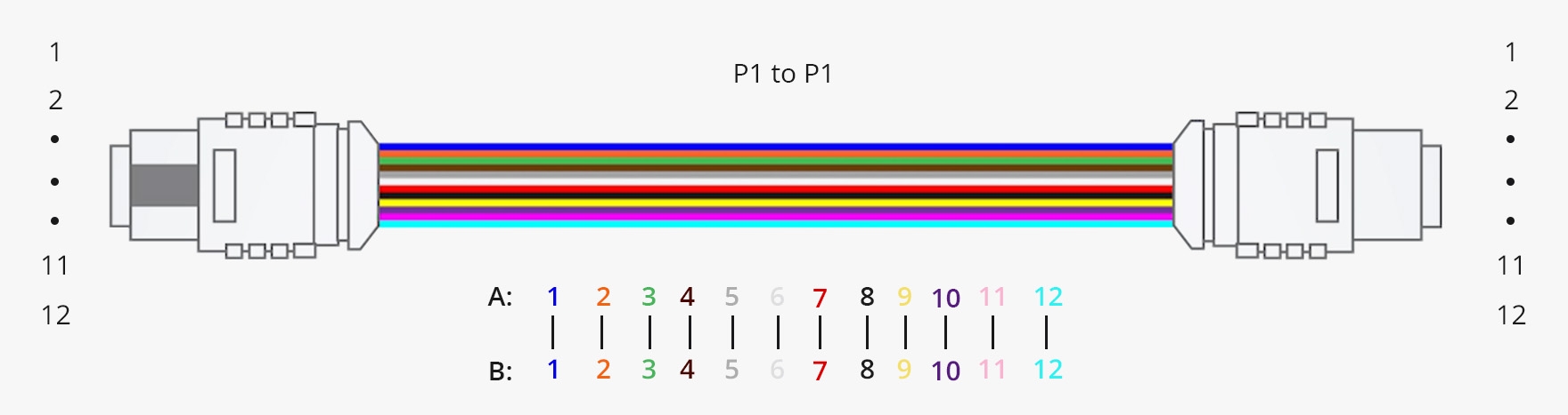
Figure 1: Fiber sequence of MTP/MPO-12 Type A cable
MTP/MPO Type B cable is a "reversed" cable: the fiber order is flipped, so position 1 at one end connects to the opposing position at the other end (for a MTP/MPO-12 cable, 1→12, 2→11 …). Both connector keys on Type B cables are typically oriented the same way (key-up to key-up), so the reversal in fiber order is what preserves polarity for certain patching methods.
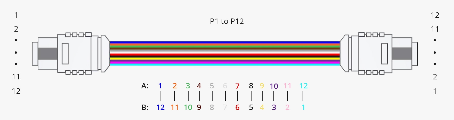
Figure 2: Fiber sequence of MTP/MPO-12 Type B cable
Note that, Type C is also a polarity type defined in the TIA-568 standard. It's often called pair-flipped, where adjacent fiber pairs are swapped along the run. For a 12-fiber MTP/MPO cable, its mapping is typically 1→2, 2→1, 3→4, 4→3 …. This "criss-cross" polarity is less efficient for parallel fiber applications and requires more complex and expensive manufacturing and testing, the Type C cables are less commonly used than Type A or Type B.
MTP/MPO Type A vs Type B Cables, How to Choose?
Connections for duplex and parallel signals are the two most common scenarios with MTP/MPO Type A vs Type B cables.
For Duplex Applications
This method is typically deployed with MTP/MPO to LC cassettes with MTP/MPO Type A or B MTP/MPO cables. This setup seamlessly converts the MTP/MPO interface into standard duplex LC ports on the front side of the cassettes. Finally, standard duplex LC patch cords (often A-to-B polarity) are used to connect the cassette ports to the network equipment.
MTP/MPO Type A in Duplex Applications
As illustrated in the Firgure 3, an MTP/MPO-12 Type A cable seperately connects two MTP/MPO to LC cassettes Type A and Type AF on each sides to maintain the channel's polarity. The Type A cable, with its key-up to key-down flip, works in conjunction with the cassette's internal wiring to ensure the correct transmit (Tx) and receive (Rx) signals are delivered to the corresponding ports on the transceivers, establishing a continuous and error-free duplex channel.
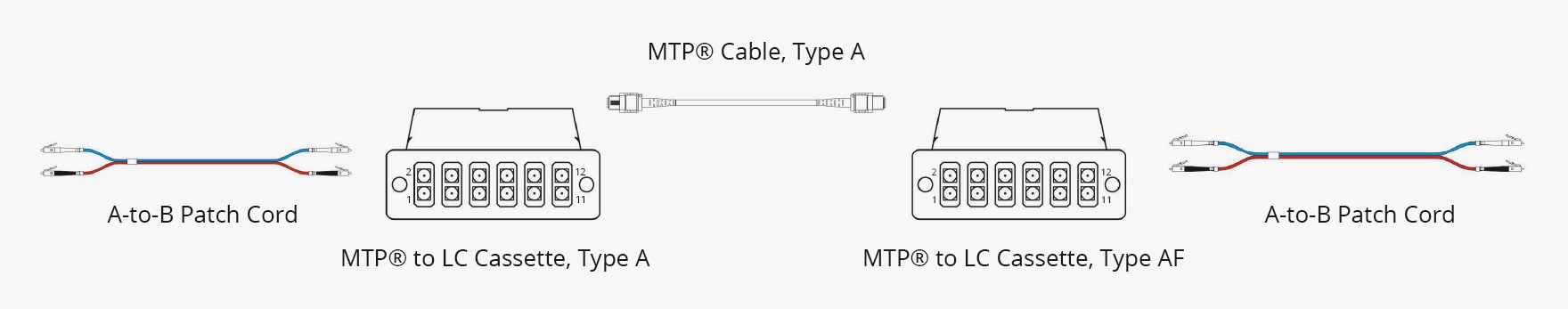
Figure 3: MTP/MPO-12 Type A for duplex signal
MTP/MPO Type B in Duplex Applications
This setup deploys one Type A MTP-to-LC cassette on each side. Connecting them is a Type B MTP-12 cable, which is characterized by its internal fiber reversal, where the fiber sequence is flipped from one end to the other. This link creates a continuous "straight-through, flipped, straight-through" signal path, resulting in correct TX/RX pairing end-to-end.
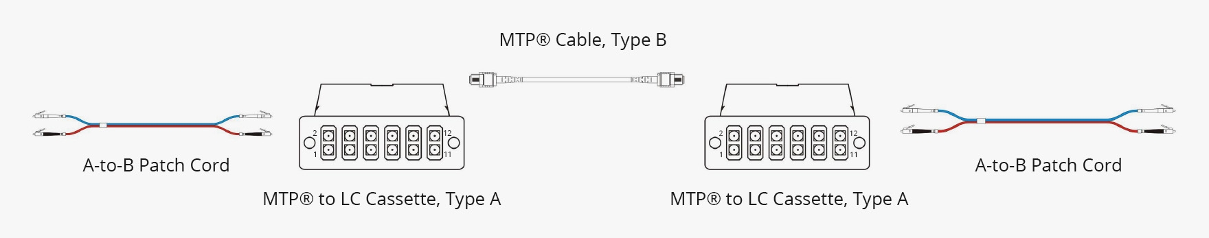
Figure 4: MTP/MPO-12 Type B for duplex signal
For Parallel Applications
For parallel optic applications, such as 40G SR4, 100G SR4, and 400G SR8, where multiple fibers simultaneously transmit and receive discrete data streams, maintaining a consistent and straightforward polarity path is critical. The following are MTP/MPO Type A and Type B connections.
MTP/MPO Type A in Parallel Applications
This complete channel is established as follows: MTP/MPO Type A cable → MTP/MPO panel Type A (key up to key down)→ MTP/MPO Type A cable → MTP/MPO panel Type A→ MPO Type B cable. The final Type B MTP/MPO cable at the endpoint provides the polarity reversal required by the parallel transceiver, thus TX/RX channels align end-to-end.
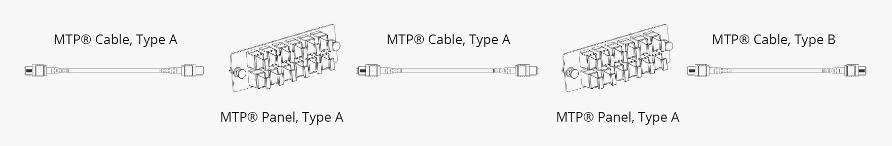
Figure 5: MTP/MPO Type A cable in parallel links
MTP/MPO Type B in Parallel Applications
The full chain runs: Type B MTP/MPO cable → MTP/MPO panel Type B (key up to key up) → Type B MTP/MPO cable → MTP/MPO panel Type B (key up to key up) → Type B MTP/MPO cable. Because every cable and panel implements the reversed fiber mapping, the reversal is preserved end-to-end, so parallel transceivers receive the correct TX/RX pairing.
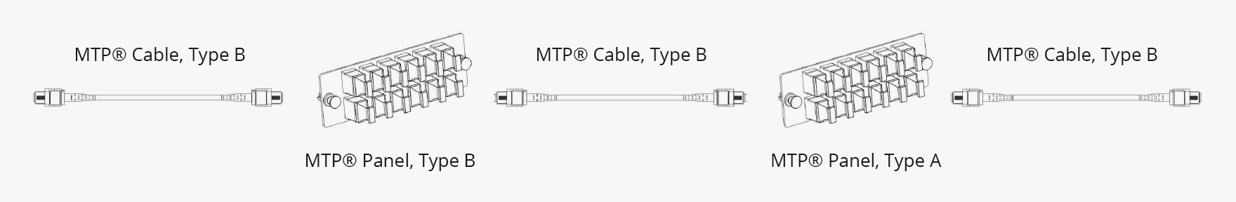
Figure 6: MTP/MPO Type B cable in parallel links
To provide a clear and quick reference, the following table summarizes the key characteristics and typical applications of both MTP/MPO Type A and Type B polarity methods.
|
|
Cassettes |
MTP/MPO Cables |
Fiber Patch Cables |
Transmission of the Signal |
|
Method A |
Different (One Type A & one Type AF) |
Straight Through (Type A) |
Same (A to B) |
P2 in and P1 out |
|
Same (Type A) |
Straight Through (Type A) |
Different (One A to B & one A to A per duplex channel) |
P2 in and P2 out |
|
|
Method B |
Same (Type A) |
Cross Over (Type B) |
Same (A to B) |
P2 in and P11 out |
|
Different (One Type B1 & one Type B2) |
Cross Over (Type B) |
Same (A to B) |
P2 in and P1 out |

